Plotting for Improvement
It’s something a lot of community radio stations here in the UK are trying to improve – their FM coverage footprint. While the 25 watts ERP that Ofcom often licence stations at is usually “good enough” to cover most of the patch, there’s often areas where coverage could be improved to match the editorial area the station would like.
In all cases I’ve had a hand in, terrain is the biggest issue. Turns out that the VHF transmissions just won’t penetrate through hills, resulting in “dead” zones in adjoining valleys. The main solutions in those cases are to gain height or relocate the transmitter. This isn’t always possible and there are a few other tricks we’ve been looking at recently.
While it would be amazing to just be able to buy any replacement antennas (and associated transmitter/amp in some cases) and just test these options, it’s just not practical in our current licensing regime. Any changes we’d want to make to the transmission system (antennas, locations, etc.), need to be passed by OfCom and probably would involve getting through commissioning. That’s a lot of time and effort for something that may not make that much of a difference.
That’s why we’ve spent a lot of time using Radio Mobile to plot possible options. While it can’t 100% accurately predict everything and we can’t model mixed polarity options (without resorting to some guesswork), it’s proved a useful exercise. Modelling co-channel interference, which can be a real problem for community services, is also problematic.
Before we get much further into this, I should admit that I have talked about making predictive plots before. Turns out I’d been making a few mistakes in using that process which often resulted in pessimistic plots.
Firstly, I’d been working in EIRP rather than ERP. A silly mistake but one I’m not making any more.
Another issue to consider is receiver sensitivity and what field strength levels are considered “good enough” for planning purposes. Turns out that the ITU provide some guidelines to help. For rural coverage, which the station I’ll be using in later examples is after, a level of 48 dBµV/m for mono service is suggested. For stereo service, a higher level of 54dbµV/m is suggested. This matches some commercially produced plots I’ve seen in the past.
In terms of the receiver, I’ve been modelling with a dipole 10m above ground level. This derives from some old BBC standards and gives a good rough guide for mobile coverage. We can do this as car radios are far more sensitive nowadays. In reality, we still end up with a slightly pessimistic plot for mobile coverage but nice trade-off between outdoor and indoor.
In Radio Mobile, it’s possible to model different antennas on both the transmitter and receiver but having them as part of the same network but operating different systems.
And on that note, I think we’re covered enough of the groundwork. Let’s look at some real examples. For this, we’ll be looking at a community radio station in the Midlands. They’re currently located and licenced to operate out of Ilkeston but have always intended to cover the borough of Erewash, including Long Eaton. Their current transmitter is located on some high ground in Ilkeston and operates at 25W ERP with a monopole antenna.
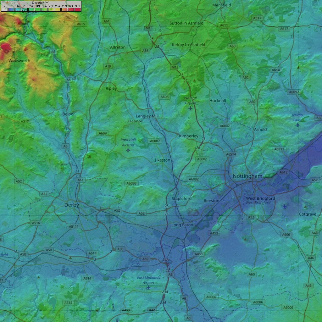
That last bit’s important but let’s look at why they’re struggling to get into Long Eaton right now. A good place to look is a terrain map, pulled out of Radio Mobile and the STRM data.
There are a couple of points to note from the image. Firstly, the area with poor coverage is in a valley created by the River Trent. It’s at a lower elevation than the transmitter location but in the shadow of a bank of hills.
While moving the transmitter to this bank of hills would significantly improve coverage in that area, Ilkeston itself is a small hill. You’ll end up with Cotmanhay in the shadow of this hill, losing coverage in an already covered area. Being the location of the studios, it would be a hard option to take on.
The problem could indeed be countered by increasing the elevation of the transmitter. Something that would come at significant cost as there’s no tall buildings in that area to take advantage of.
We’d also have the practical problem of point-to-point STLs becoming unfeasible. While a line fed transmitter could tackle this issue, it would be an ongoing cost that would need to be considered.
Another possibility that could be consider when looking at this map would be up in the north west, towards Matlock. Unfortunately, it’s well out of area and and we’ve only got 25W ERP to play with.
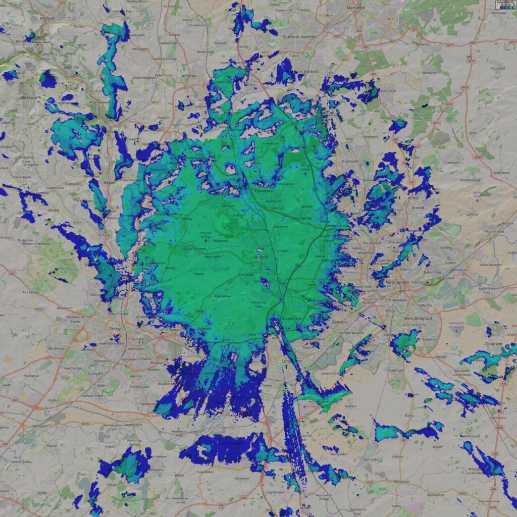
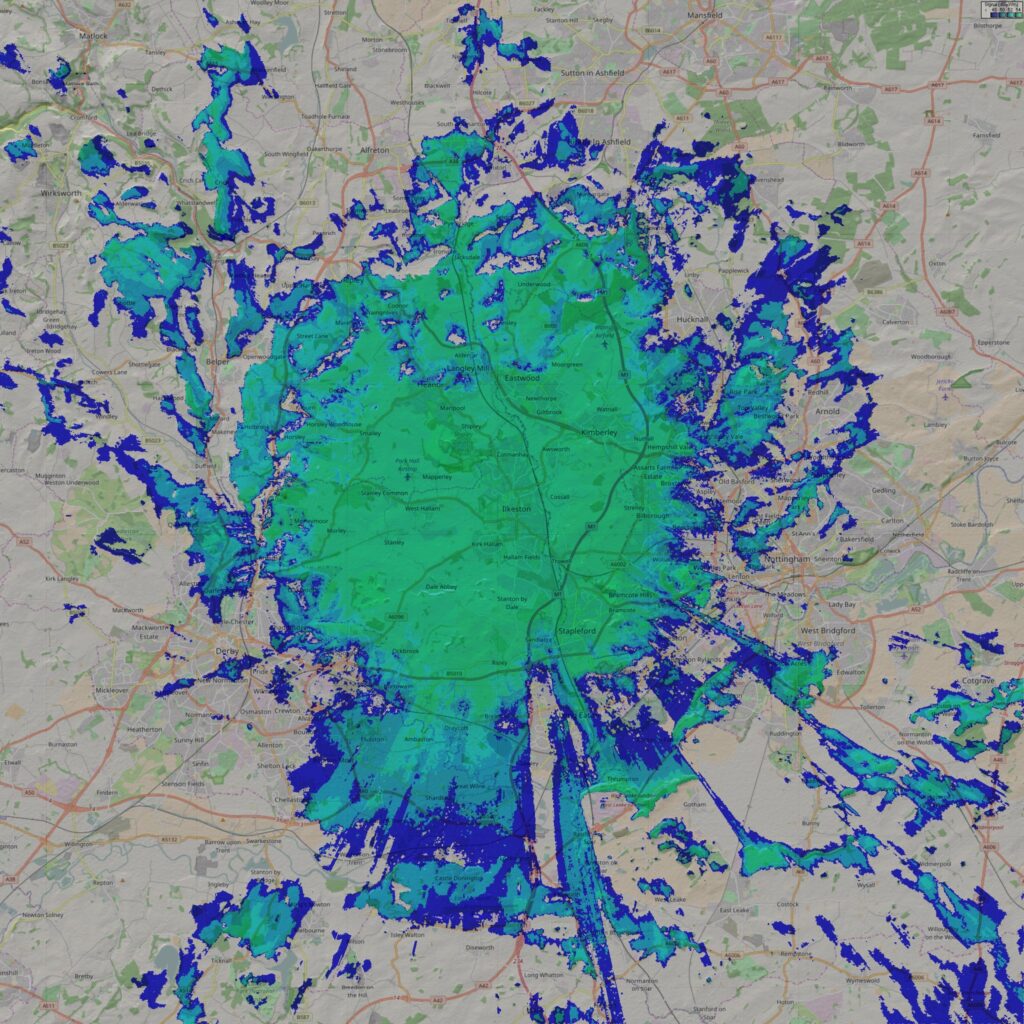
On that basis, let’s have a look at what changing an antenna can do. To start with, let’s generate a predictive plot that demonstrates the coverage obtained with the current antenna – a monopole on a rooftop. This is actually a surprisingly hard thing to model accurately. There have been studies into the behaviour of monopole antennas with the result basically being a bad thing for our station. The result is a doughnut (much like a dipole) but tilted above the horzion. Not so good for hitting those fringe areas on lower ground.
Either way, a rough plot of what a monopole at 25W ERP does looks something like this:
It’s a surprisingly accurate plot. Coverage goes from solid to patchy where the boundaries are on the plot. While car radios will continue to receive the service, it becomes subject to fuzz/hiss/loss and even co-channel interference from a national broadcaster’s service in Wales. Admittedly, the holes in coverage near the transmitter are nowhere near that bad, it’s a good indication of what’s going on at the fringes.
One of the interesting things to note is that while a monopole will happily “paint” high terrain a fair distance out, low lying ground loses out – badly.
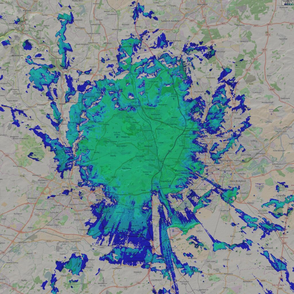
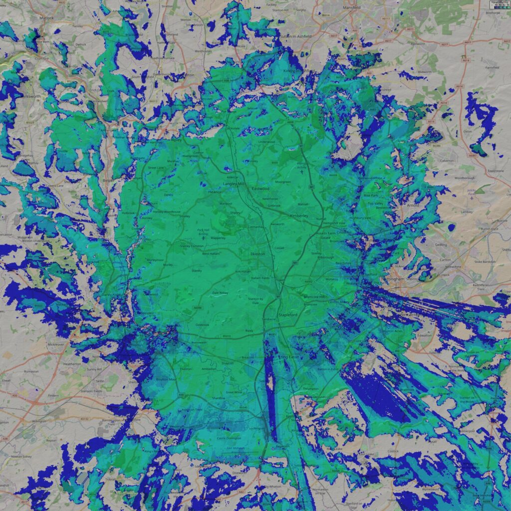
A simple fix for this would be a to swap the monopole for a dipole. With that, we’ll see more power directed below the horizon. The result looks something like this:
Who’d have thought a simple antenna change could have such an effect on the prediction! More of the Long Eaton area to the south is covered – exactly what we’re looking for. Though not a lot can be done about the real low-lying terrain that the Erewash Canal runs along.
An interesting point to note here is that we now have areas with mono coverage. The cut-off with the monopole antenna was far more strict. We now have some gentler degradation of signal on the fringes.
This is all good but can we do better. What about going mixed polarity through the likes of the Skymasts Lindenblad antenna. It’s an expensive bit of kit, being an array of four tuned dipoles, slanted to provide the effect of going mixed polarity.
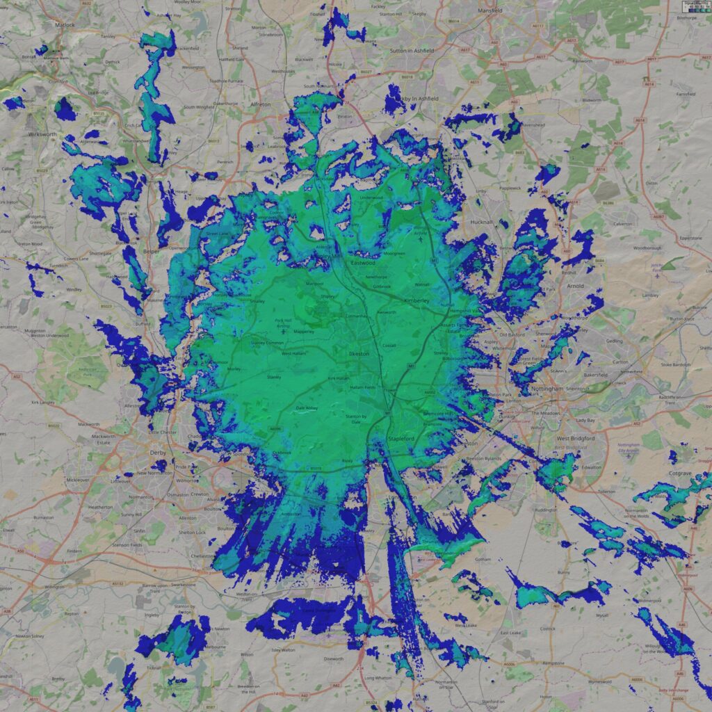
Well, let’s plot it. Using the manufacturer’s specs as a guide for both gain and radiation pattern, we end up with something like this:
Hang on a minute, it’s not much different than the dipole plot. You end up with a stronger signal in good coverage areas but things can be weaker on the fringe. That’s because we’re being a little naive.
We’ve only plotted the vertical polarity coverage of the antenna. While we can’t plot the horizontal component as well (another 25W ERP), we can “fudge” the effect. By giving the antenna somewhere between 1 and 2 dB of extra gain, we can demonstrate the possible benefit going mixed could bring us.
And with that we see an improvement in the fringes. A little bit in the area we really want to improve but much more to the north. Unfortunately, that’s the wrong direction for the editorial area.
Let’s try one more thing. OfCom are considering the idea of simplifying the the process for requesting transmission improvements. What would happen if we managed to take advantage of that to get a power increase to a modest 50W+50W?
There’s a bit more all-round improvement here. Coverage to the south still isn’t perfect but it’s a lot better. There’s still terrain shielding effects happening though.
The only real workaround for that would be a relocation and mast build (hugely expensive) or a low power relay for the low lying areas. The catch with that is you’d need a spare frequency to do this with.
It may be possible to keep cranking the power but it’s not a hugely practical solution. Overall, it seems like we may be able to make some small, simple improvements but will never get the perfect answer.

interesting article, out of interest what settings are you using in radio mobile? i do tend to find that its a tough one to get it even modestly representing the coverage area well. and its always interesting to see how others are doing the same thing
A couple of things I found make a surprising difference in Radio Mobile are the terrain data used and the step size for the plot (0.1 degrees).
In terms of RF settings, I’m plotting down to the levels in the article. You can set these as thresholds in the Single Polar Coverage plotting screen.
I’ve got the units set up as part of a single network operating two systems. The TX system has 25W ERP (or whatever you’re setting) with an appropriate antenna pattern and gain. I don’t bother setting the antenna height here and worry about line loss later (set it to 0dB/m). On the unit properties for the system is where I set the antenna height.
The sensitivity is set to 54 micro volts. Realistically, this is only useful on point-to-point plots where I’m looking at calculating link budget for a data link. Generally, fresnel is more of a worry there anyway.
The RX has similar properties but uses and omni antenna at 10m AGL. This simulates the old BBC model used by almost everyone but provides a good indoor coverage guesstimate for portable receivers. As you know, in-car coverage is always much better. 😉
That’s about as exciting as it gets. I know a colleague has found that plots can vary a bit depending on how zoomed in you are to the map.
Overall, I’ve found it a good tool for pointing out and trying to get round terrain issues. Even if, as with anything in RF, the prediction isn’t 100% spot on.